

Technical Info :: Handling and Installation
361-572-4040
Download Handling & Installation File (*.pdf)
HANDLING AND INSTALLATION INSTRUCTIONS
DISCLAIMER: All equipment manufactured by Diamond Fiberglass includes a copy of the latest version of the Handling and Installation recommendations with the shipped goods, and which may be updated from time to time without notification. The following is provided for convenience only and not guaranteed to be the latest version. Use the version shipped with the goods for updates and latest recommendations. Diamond Fiberglass makes no representations or warranty as to the accuracy or completeness of this information.
The following Diamond Fiberglass handling and installation instructions are designed to help customers install fiberglass tanks and equipment properly and in a minimum of time. Proper handling and installation are extremely important in preventing premature failure and lowering maintenance over the tank life. Handling and installation instructions outlined in this document are only recommendations and do not relieve the Purchaser from full responsibility for the proper inspection, handling and installation of the tank. Unknown situations and conditions not covered in these instructions are also the responsibility of the Purchaser. Failure by the Purchaser to take the precautions outlined in these instructions will invalidate the tank warranty.
Shipment via Diamond Fiberglass truck will be considered complete when the truck arrives at the jobsite and prior to removal of the tanks by the Purchaser. Diamond Fiberglass employees or representatives will not direct nor be responsible for the removal of tanks from commercial or Diamond Fiberglass’ own trucks. The presence of a Diamond Fiberglass employee or representative at the delivery or installation site does not relieve the Purchaser of any of his responsibility for the proper handling and installation.
PREPARATION FOR SHIPMENT
Diamond Fiberglass will take reasonable precautions when preparing a tank for shipment to prevent shipping damage. Normally, our tanks are shipped on our own trucks. Small, open top, vertical vessels will not be covered for shipment unless so specified by the customer. Movement will be by lifting lugs, if specified, in the case of closed top tanks, eye bolts in the case of open top tanks, or the tanks may be installed on a pallet. If the tanks are installed on a pallet, they will be bolted or strapped to prevent movement. Large vertical and horizontal tanks are shipped in a horizontal position.
INSPECTION
The customer should arrange for an inspector or a responsible person at the jobsite to inspect and supervise the offloading of the tank.
If damage has occurred during transit, it should be noted on the bill of lading prior to signing acceptance.
If damage has occurred, a claim should be filed promptly with the delivery carrier by the Purchaser. If no claim is filed, the customer accepts all future responsibility for a damaged tank. If damage has occurred and is not first repaired by Diamond Fiberglass prior to the tank being put into service, the Purchaser accepts all future responsibility for the effects of tank failure resulting from such damage.
RECEIVING INSPECTION
The following should be used as a guideline in inspecting the tanks prior of offloading. Inspection should be made both inside and out.
- Check the load for any signs of breakage, abrasion, shifting or rotation that may have resulted in damage to the tank.
- If shipping cradles are used, check for any signs that they may have moved, shifted or rotated resulting in cracks or crazes at point of contact.
- Check each fitting for cracks, gouges, and dents. All fittings should be secured to the tank without any play. If any of the fittings are able to move when testing force is applied to them, contact Diamond Fiberglass.
If significant damage is discovered on the tanks or pipes, contact Diamond Fiberglass before attempting to unload the material. If a tank must be unloaded immediately, do not set it in the vertical position as it would make the damage much more difficult to access and repair.
GENERAL HANDLING INSTRUCTIONS
Diamond Fiberglass tanks are designed to withstand normal handling procedures. Here are some normal precautions to follow to prevent damage to the tank.
- Operators of hoist equipment should follow proper rigging procedures always. Care should be taken to prevent the tank from swinging out of control.
- Always lift – never roll or slide a tank.
- When moving a tank, do not drop or allow hard impact.
- Never let tools strike or drop on either the inside or the outside of the tank.
- Ladders used inside the tank must use rubber foot protectors.
- Workmen entering a tank should wear soft-soled shoes.
- Never use cables or chains around the tank.
- Never lift a tank by using any fittings or appurtenance other than the lifting lugs. When lift lugs are not provided as part of the equipment, woven fabric rigging slings of 3-inch minimum are recommended.
- In storing tanks prior to installation, tiedown securely. Tank should be placed only on firm level surfaces which are free of stones, tools and other small hard objects. Tanks should be stored horizontally and supported on the top and bottom “knuckle” ends only and never in the middle of the sidewall. When stored outdoors, tanks should be adequately secured to prevent movement due to wind or water flotation.
- Do not allow cables, hooks or spreader bar to swing against the tank.
NOTICE – Diamond Fiberglass does not prepare lifting plans for customers nor make recommendations on the size and type of lifting equipment to use. However, it is generally recommended that as part of lifting plan preparation, an additional 20% contingency should be added to the design weight of the vessel to account for manufacturing variances. If a certified weight is needed for your lifting plan, please reach out to Diamond Fiberglass prior to shipment of the equipment.
UNLOADING
A spreader bar and lines to appropriate lifting lugs, or a clevis and lines to lifting lugs shall be used to unload tanks shipped on a flatbed trailer or one of our specially designed padded saddle trailers. The angle between the lifting lines and top of tank must always be 60o or greater. When lifting lugs are not provided, tanks should be lifted off using two canvas or nylon slings or straps and a spreader bar, which is attached to the hoist cable.
Large tanks should be righted by hoisting with a spreader bar and lines to the lifting or clevis and lines to lifting lugs. If a tailing lug is not present on the tank, a choker sling can be used on the bottom ¼ of tank sidewall as a tailing line. If the vessel has any extruding fixtures and/or insulation near its bottom end, place the choker sling below them if possible. Adequate padding is necessary to protect the pivot point. Never use the anchor lugs to tail the tank. Workmen should keep control over the tank with guidelines to ensure the tank is gently brought to rest upon its base. Once upright, use a spreader bar and lines or clevis lines to appropriate lifting lugs to move tank into position. Ensure size of lifting equipment, lines, clevises can handle the weight of the tank. Open top tanks may require internal bracing during lifting to prevent damage due to distortion.
ON-SITE STORAGE (Before Installation)
- Vessel can be stored in either the vertical or horizontal position, whichever site conditions allow.
- Should the vessel be stored in the vertical position, it must be anchored or tied-off to prevent it from overturning. The vessel’s lower flanges can be blinded, and the vessel filled with 1 to 2 feet of water to weigh it down. If preferred, the vessel lifting lugs can be used as “guy” points to tie the tank off to anchor points. If water is used to weigh the tank down for storage, precautions should be used per the “INSTALLATION” portion of this document to protect the bottom of the tank from damage.
- Should the vessel be stored in the horizontal position, it should be tied-off or strapped to prevent rolling due to wind. In the absence of saddles that are designed to fit the arc of the tank, standard flat bottom, dome or flat top tanks can be set directly on the ground, provided fittings and accessories do not interfere. Chock the vessel with wood blocks, tires, etc. at the top and bottom knuckles. Only the top and bottom knuckles of the tank should be in contact with the ground. Do not set the vessel on blocks or timbers, especially if they are away from the top and bottom knuckles. Use ropes or nylon straps to tie-off the vessel. Do not use cable or chains.
- Leg supported cone or dish bottom vessels can be stored either vertically or horizontally. Should they be stored either vertically or horizontally, the same procedure above can be used. Once the vessel is set, the support legs can be blocked, chocked, or tied-off to prevent roll-over.
- Skirt supported or open top tanks with stiffening “leg-out” flange(s) stored in the horizontal position must have the ground “trenched out” to allow for the flange, to prevent the load of the vessel being carried by the flange. If this is not possible, the vessel may be set on soft blocks (tires, foam board, etc) provided the blocks are set adjacent to the stiffening flange(s). If this is not possible, the vessel must be stored vertically, and tied-off as previously noted to prevent overturning.
- If a large open-end tank is stored horizontally, a vertical brace at the open end may be required to prevent excessive distortion. The ends of the brace should be padded to decrease contact pressure.
- Closed tanks should not be sealed completely (airtight).
- If freezing conditions are possible, measures should be taken to prevent water from accumulating inside tank or pipe.
BEFORE USE
It is the customer’s responsibility to inspect the interior of the tank or vessel for contaminants such as mylar film, excessive dust, manufacturing tools or equipment, or any natural contamination that has accumulated during storage before installation.
INSTALLATION
- The support base for flat-bottomed vertical vessels should provide full and uniform support over the entire bottom area. The support base should be properly designed to prevent settling or deflection under maximum design loads.
- The support base surface should be nonporous and free of cracks, depressions and vertical projections. Reinforced concrete, trowel finished to American Concrete Institute Specifications (ACI- 301-72, Section 11.7.3, “Trowel Finish”) is often used as a support base.
- Vertical equipment having a cone or dished bottom will have an alternate type of mounting arrangement such as an FRP or steel skirt, or legs. These must be considered as special cases, for each unit will have its own condition of load concentration. Special support design is therefore required for each individual installation.
- Each flat bottom unit should be set on a cushioning pad to minimize stresses caused by seams, shrinkage distortion, and/or support base irregularities. Where irregularities are less than 1/2 inch (12.7 mm) in depth; several layers of 30 lb. roofing felt equal in diameter to the outside diameter of the equipment plus 2 inches (0.0. + 2 in.), should be laid directly on the surface of the support base. The center of the pad should be built- up by the addition of two layers of the same material, one equal in diameter to 1/2 and the other, 1/4 the diameter of the equipment, Figure 1.
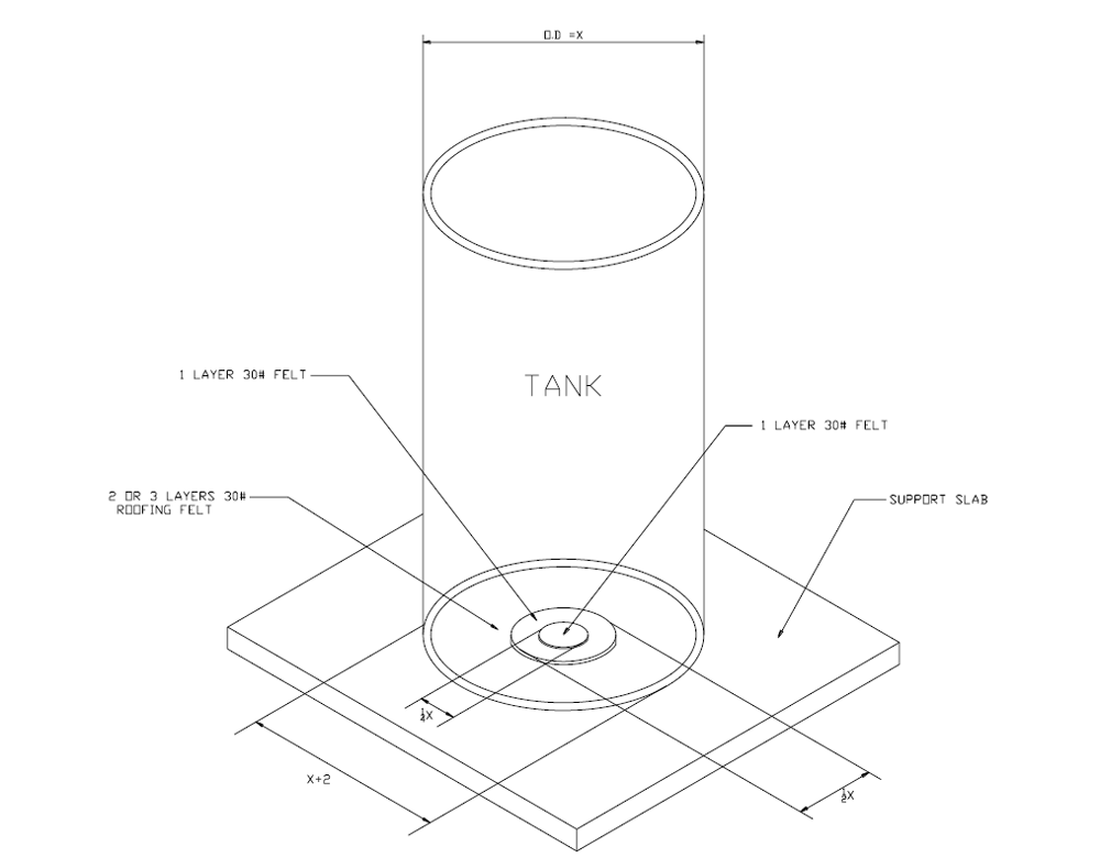
Figure 1 – Roofing Felt Placement On Slab
- A suitable elastomeric sheet material of proper environmental resistance may be substituted for the roofing felt. 1/2” thick or 3/4” 60 durometer neoprene often works well if suitable for chemical resistance.
- Where irregularities in the surface of the support base are greater than 1/2 inch (12.7 mm) in depth, an asphalt type of paving mastic can be troweled into these areas and pressed or tamped to provide a reasonably hard, flat and level surface. Time should be allowed for the mastic to harden before the first layer of roofing felt is applied.
- Where a vessel has a bottom drain, provisions should be made in the base pad with clearance so that contact will not occur between the pad, the nozzles or nozzle flange.
- Where a trench in a base pad is required to accommodate bottom discharge piping, a structural trench cover should be installed flush with the top of the base pad to minimize the unsupported area of the tank.
- All flat bottom equipment should be secured in place by anchoring to the foundation through hold down lugs. After setting the tank, install bolting and single nut, HAND TIGHTEN ONLY, fill tanks with water, then either:
-
- grout under the lug with non-shrink grout and torque to 25 ft-lbs; or,
- double nut to prevent the bottom nut from backing off.
DO NOT torque down lug bolting until tank is filled and grouted. Failure to follow this procedure can result in a premature bottom failure.
-
- It is recommended that all vessel nozzles below the liquid level should be joined to piping through a flexible connection.
- Valves, which are attached to tank nozzles, must be full-face flanged, and should be independently supported so that closing and opening of a valve does not transmit the total torque load directly to the nozzle. It is NOT recommended to install non-flanged “sandwich” valves between the tank nozzle flange and connecting pipe flanges. To do so may damage the tank nozzle.
- Flanged nozzles have standard ANSI 150 Lbs. flange bolt hole arrangement. Full-face mating flanges and gaskets are to be used. Gasket material exceeding 70 durometer (and less than 1/8″) should not be used. Raised face flanges, wafer style flanges or ring type gaskets should not be used.
WARNING – Raised faced or wafer style flanges for pipe or valves mating to a FRP flat faced flange are not recommended due to the stress placed on the FRP flange during installation. If anything other than flat faced flange must be used, the mating flange should be modified to be flat faced (for example by using a compensation ring or other device) to prevent bending of the FRP flange during bolt up. If a flat surface is not provided, cracking of the FRP flange may occur due to improperly mating and this is not covered under the manufacturer’s warranty. - Metal washers should be used under all bolt heads and nuts, which would otherwise be in contact with the FRP flanges.
- Nut and bolt threads should be lubricated before tightening.
- Bolting take-up torque should be applied uniformly, alternating 180 degrees and rotating as near 90 degrees as possible in a typical flange makeup “star” pattern. A bolt torque pressure of 25 ft. Lbs. will normally be sufficient to affect a seal. If you are having sealing issues, please contact Diamond for recommendations before torquing above 25 ft-lbs
- Precautions must be taken by the customer to ensure the supplied vent is not restricted in any way during the service life of the vessel. The customer is solely responsible for ensuring adequate venting is achieved. Modifications to the originally supplied vent must not be made without consulting Diamond Fiberglass.
ACCESSORIES AND TANK ATTACHMENTS
- Agitators, mixers, coils, etc. must be adequately supported as approved by Diamond Fiberglass.
- External piping and/or accessories (such as but not limited to sight level gages, immersion heaters, spargers) attached to the vessel must be adequately supported to ensure that stresses are not imposed on vessel nozzles. The design and supply of these external supports is the responsibility of the customer.
VESSEL ENTRANCE PRECAUTIONS
- Before allowing personnel to enter vessel, be certain that all applicable confined space entry procedures are being complied with.
- Ensure that all valving and plumbing is either disconnected or “locked out” before allowing vessel entrance.
- Ensure that vessel is adequately vented.
- Be sure any foreign objects, dirt, pebbles, etc., are removed from the vessel so they will not mar the interior surface.
- Personnel entering the vessel should wear soft soled shoes, free from any debris that could injure the interior surface (pebbles, nails, etc.).
- If a ladder is used for entrance, it should have padded feet. Do not rest the ladder on the internal components or point load its base surface.
- Care must be taken not to drop or bang objects against the vessel.
- When walking in the vessel, make sure any areas which flex do not rest against sharp objects. Use padding where necessary.
- Never use any component, internal or external, for climbing or standing unless it is specifically designed for this purpose.
DISPOSAL
- After the service life of the equipment, dispose in accordance with local codes.